ProjectsMicrochannel cold plate
A microchannel cold plate at 100 W/cm²
A water-cooled copper cold plate for a 20 × 20 mm die dissipating 400 W, laid out two ways that share everything but the path the water takes. At the same flow, serpentine channels run the die 3 to 6 K cooler with less than half the temperature spread. At the same pumping power, straight channels run cooler.
- Heat load
- 100 W/cm² over a 20 × 20 mm die (400 W), 60 °C limit on the die
- Plate
- Copper; 0.30 × 2.0 mm channels between 0.20 mm fins at 0.50 mm pitch
- Coolant
- Water in at 25 °C, 0.2 to 2.0 L/min
- Method
- Steady 3-D conjugate heat transfer CFD, 14 runs, with a three-level mesh study
The design
The target is a die that stays at or below 60 °C while it dissipates 100 W/cm² over 20 × 20 mm, cooled by water entering at 25 °C. That is the heat flux of a high-power processor, and it leaves 35 K between the coolant and the silicon. Both plates share the copper body, the channel cross-section and the heat load. Only the flow path differs.
| Item | Value |
|---|---|
| Heat load | 100 W/cm², uniform over a 20 × 20 mm die on the plate underside (400 W) |
| Plate | Copper C101, k = 390 W/(m·K); 1.0 mm base under the channels, 0.5 mm lid bonded to the fin tips |
| Channels | 0.30 mm wide × 2.0 mm deep (aspect ratio 6.7), hydraulic diameter 0.52 mm |
| Fins | 0.20 mm thick at 0.50 mm pitch, 40 channel slots across the die |
| Straight layout | 40 parallel channels, 22 mm long (1 mm unheated at each end) |
| Serpentine layout | 10 parallel serpentines on the same 40 slots, each four passes joined by three U-bends with a 0.3 mm turn gap; inlet and outlet on the same edge |
| Coolant | Water at 25 °C; viscosity and conductivity follow the local temperature |
| Boundaries | Plug inflow, outlet at zero static pressure, no-slip walls, all outer faces adiabatic |
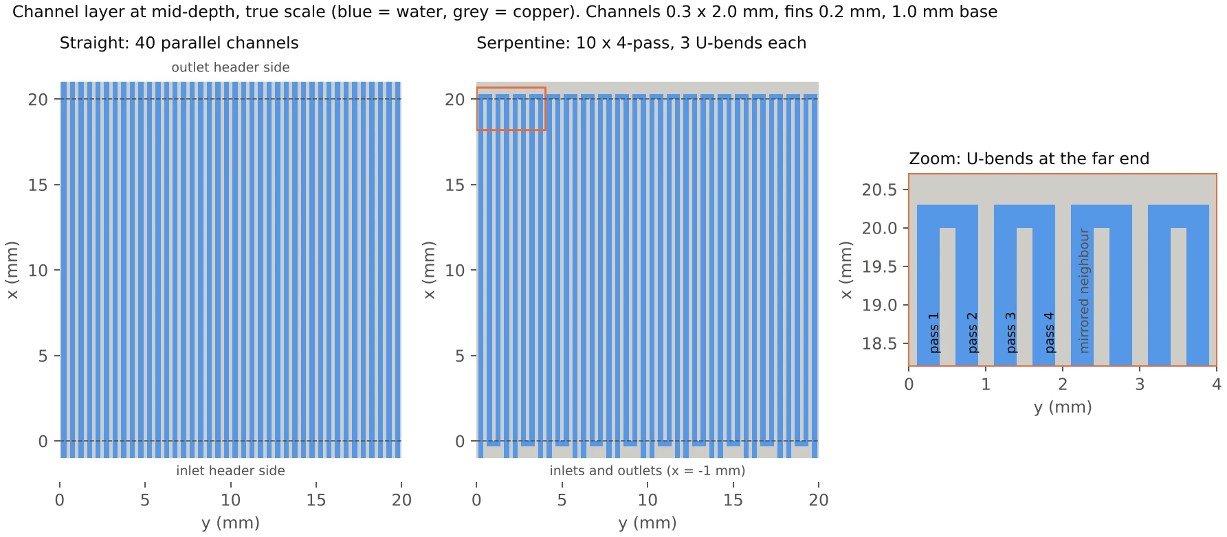
The channel width came first. A correlation model showed that with laminar water, 1 mm channels run above 100 °C at any flow up to 1 L/min, and 0.5 mm channels still exceed 60 °C at 1 L/min, which pointed to 0.3 mm. One continuous serpentine through all 40 slots would run turbulent, at a Reynolds number near 9,700, and need about 12 MPa at 0.5 L/min. The serpentine is therefore ten short four-pass serpentines in parallel.
Side by side at 0.5 L/min
At the same total flow, the serpentine runs 5.2 K cooler, with less than half the temperature spread across the die, and pays 23 times the pressure drop.
| Metric | Straight | Serpentine | Serpentine vs straight |
|---|---|---|---|
| Max die temperature | 53.4 °C | 48.3 °C | 5.2 K cooler |
| Die temperature spread | 15.0 K | 6.4 K | 57% smaller |
| Mean die temperature | 49.0 °C | 46.7 °C | 2.2 K cooler |
| Outlet water temperature | 36.6 °C | 36.6 °C | Same (energy balance) |
| Thermal resistance, die max to inlet | 0.071 K/W | 0.058 K/W | 18% lower |
| Heat load that reaches 60 °C | 492 W (123 W/cm²) | 602 W (150 W/cm²) | 22% more |
| Core pressure drop | 0.81 kPa | 19.0 kPa | 23× |
| Pumping power, whole plate | 6.8 mW | 159 mW | 23× |
| Water velocity in a channel | 0.35 m/s | 1.39 m/s | 4× |
| Channel Reynolds number | 231 | 944 | 4.1× |
| Wall heat transfer coefficient | 8,650 W/(m²·K) | 12,300 W/(m²·K) | 42% higher |
| Nusselt number (on Dh) | 7.3 | 10.4 | 42% higher |
The heat transfer rate is fixed at 400 W by the applied flux, so the table compares how much load each plate could take before the die reaches 60 °C, scaling the temperature rise linearly. The heat transfer coefficient is the heat crossing the wetted walls along the heated length, divided by the wetted area and the mean wall-to-bulk temperature difference.
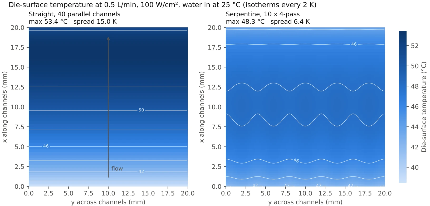
The straight plate heats steadily along the flow and peaks 17 mm from the inlet side, short of the die edge, because the copper conducts heat into the unheated last millimeter. The serpentine's peak sits in the middle of the die, with ripples at the 4 mm serpentine pitch.
Flow sweep
Swept from 0.2 to 1.0 L/min, and on to 2.0 L/min for the straight plate, the serpentine holds the die at 60 °C from 0.25 L/min, against 0.30 L/min for straight channels. Its margin grows from 3.0 K at 0.2 L/min to 6.0 K at 1.0 L/min. Heat transfer in the serpentine's entry regions keeps improving with velocity, while the straight channel's is close to fully developed.
Pressure drop
The price is pressure. At equal flow the serpentine's core pressure drop is 17 to 31 times that of the straight channels, and the gap widens with flow, because the serpentine's drop grows as Q1.56 against Q1.19 for straight channels.
Each U-bend costs about 1.9 velocity heads, rising from 1.85 at a Reynolds number of 490 to about 2.0 at 1,740. The loss coefficient comes from the pressure field, as the jump between the two passes' pressure trends extrapolated to the bend, so it includes the extra loss while the flow redevelops after the turn. The bends carry 21% of the serpentine's pressure drop at 0.25 L/min and 40% at 1.0 L/min.
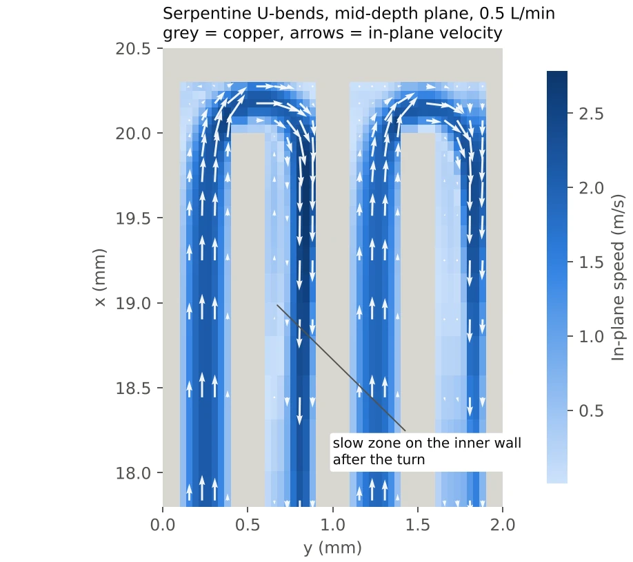
That restart of the boundary layers after every bend is what lifts the serpentine's heat transfer, and it is also where the bend loss comes from.
Equal pumping power
Comparing the layouts at equal flow flatters the serpentine. Holding the die at exactly 60 °C takes 2.2 mW of pumping power with straight channels (0.30 L/min at 0.44 kPa) against 26 mW for the serpentine (0.25 L/min at 6.4 kPa), about 12 times more. For any given pumping power, the straight plate runs cooler.
Straight channels are therefore the default. The serpentine earns its place where coolant flow rather than pressure is the limit, or where die uniformity matters: at its 60 °C point the serpentine's die spread is 8.5 K, against about 19 K for straight channels.
Why they differ
The serpentine wins on temperature mainly because its counter-flowing passes average the water temperature under every point of the die. The straight layout wins on pumping power because laminar friction grows with both velocity and path length, and the serpentine raises both four-fold.
- Pass averaging
One serpentine packs four passes into 2 mm of width on a shared 1 mm copper floor. Conduction across that width is about 3% of the convective resistance, so the floor sees roughly the mean of the four water temperatures, which is the mid-path water temperature everywhere along the die. The straight channel's floor follows its own water, which warms 11.6 K from inlet to outlet at 0.5 L/min, and the peak lands where the water is hottest.
- Developing flow
The fully developed laminar Nusselt number does not depend on velocity, so four times the velocity alone buys nothing. The gain comes from the thermal entry length, about 0.05 Re Pr Dh: roughly 30 mm for a 22 mm straight channel, and roughly 125 mm for a 21 mm serpentine pass. Every pass runs in the high-h entry region and every bend restarts the boundary layer, so the wall heat transfer coefficient is 42% higher.
- Pressure drop
Four times the velocity over four times the path length gives about 16 times the laminar friction. Stronger entry losses and three bends take it to 23 times at 0.5 L/min.
- Pumping power
Pump power is ΔP × Q. Raising the straight plate's flow until it matches the serpentine's temperature costs less than the serpentine's pressure penalty.
Method and checks
The results come from a steady three-dimensional conjugate heat transfer model written for this study. It solves laminar, incompressible flow and energy together in the copper and the water, and it was checked against the analytical duct solution, its own energy balance and a mesh study.
- Grid
A non-uniform Cartesian finite-volume grid with staggered velocities and blocked-cell solids: 8 × 20 cells across each channel and 0.05 to 0.4 mm along the flow, refined at inlets, bends and die edges. That is 26,780 cells for one straight channel and 107,120 for one serpentine.
- Solver
The coupled velocity–pressure system is solved directly inside a Picard loop with Anderson acceleration. Convection uses a second-order van Leer TVD scheme by deferred correction, diffusion is central, and the copper–water interface uses harmonic-mean conductances.
- Properties
Water viscosity and conductivity follow the local temperature, with flow and energy re-coupled until the pressure drop changes by less than 0.3%. Density (994 kg/m³) and specific heat (4,178 J/(kg·K)) are held constant.
- Domain
One channel, or one serpentine, with mirror symmetry on both sides, scaled to the full plate (40 or 10 repeats). A straight case ran in about a minute, a serpentine case in 10 to 23 minutes, on two CPU cores.
| Check | Result |
|---|---|
| Fully developed friction in the 0.3 × 2 mm duct against Shah and London (fRe = 20.05) | −6.8% at 6 × 16 cells, −4.2% at 8 × 20, −1.9% at 12 × 32: second-order convergence |
| Energy balance, heat carried off by the water against the 400 W applied | Closes to better than 0.0001% in every run |
| Mesh, straight channel at 0.5 L/min (6 × 16, 8 × 20, 12 × 32) | Max temperature 53.24, 53.44, 53.65 °C; ΔP 0.795, 0.813, 0.829 kPa. Grid convergence index on the finest grid: 0.7% on max temperature, 1.9% on ΔP, 3.0% on h |
| Mesh, serpentine at 0.5 L/min (6 × 16, 8 × 20, 10 × 26) | ΔP 20.94, 21.57, 21.90 kPa; max temperature 48.25, 48.54, 48.61 °C. Richardson extrapolation puts the 8 × 20 mesh 3.3% low on ΔP and 0.4% low on the temperature rise |
| Streamwise spacing 0.4 mm against 0.2 mm, straight channel | Max temperature and ΔP unchanged to four digits |
The production mesh therefore reads the peak temperature rise up to 2% low and the pressure drop 3 to 5% low, in the same direction for both layouts, so the comparison holds. The correlation model used for sizing tracked the CFD within 3% on the straight plate's pressure drop and within −2.3 to +0.9 K on the serpentine's peak temperature. It reads the straight plate 2.3 to 5.4 K hot because it has no axial conduction in the copper.
Limits and next steps
- Headers
Every channel here receives exactly its share of the flow. Real manifolds starve some channels, and the straight plate, with only 0.3 to 4 kPa across its core, is more exposed to that than the serpentine at 5 to 56 kPa. Header and port losses are left out of both pressure drops.
- Repeating cell
Edge channels, the plate border and heat spreading beyond the die are not modeled.
- Die
A uniform 100 W/cm² with no hotspot and no thermal interface material. A TIM of 0.05 K·cm²/W would add 5 K to both layouts.
- Flow regime
Steady laminar flow is assumed. At 0.7 and 1.0 L/min the separation behind the serpentine's fin tips does not fully settle, although ΔP holds within 0.05% and peak temperature within 0.01 K between iterations. A transient run would show whether that region oscillates.
Next on the list: header and manifold CFD to put a number on flow maldistribution, the same geometry in Ansys Icepak or Fluent as an independent cross-check, a two-pass serpentine (the correlation model puts it at 59.6 °C and 1.4 kPa at 0.25 L/min), and a TIM layer with a hotspot in the power map.