ProjectsSplit hybrid vehicle
A split hybrid electric vehicle
We turned a compact petrol hatchback into a hybrid by giving each axle its own drivetrain. The stock petrol engine still drives the front wheels, and a battery-powered electric motor with regenerative braking drives a new live rear axle. In town the car runs on electricity alone; on the highway the engine takes over.
- Role
- Team lead; B.Tech capstone, Lovely Professional University, mentored by Varun Goyal
- Funding
- Lovely Professional University, for Auto Expo 2014, New Delhi
- Base car
- Compact hatchback, 796 cc petrol engine, front-wheel drive
- Electric drive
- 10 kW brushless DC motor, 36 V lead-acid pack, 12:1 reduction
The idea
In most hybrids the engine and the electric motor share a transmission. Ours share nothing but the road: the engine drives the front axle, the motor drives the rear axle, and either one can move the car on its own. This layout is also called a through-the-road hybrid. Keeping the two drivetrains apart meant we could add the electric side to an existing car without touching its engine or gearbox.
Each drivetrain does the job it is best at. A petrol engine is least efficient in slow, stop-and-go traffic, and that is exactly where the electric drive runs, with no tailpipe emissions, and where frequent braking gives back the most energy. On the highway the engine runs near full load, where it is most efficient, and the motor is decoupled.
Electric drivetrain
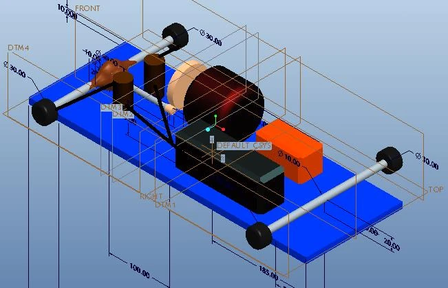
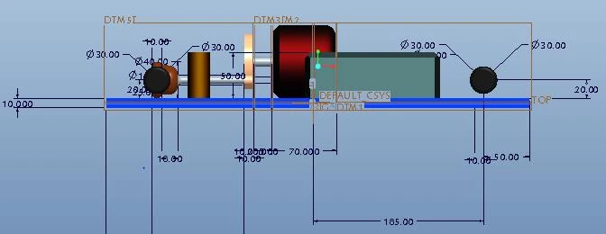
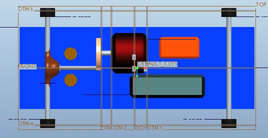
The rear drivetrain was designed around regenerative braking, since recovering braking energy is the main benefit of hybridizing a city car. A 10 kW permanent-magnet brushless DC motor drives the rear differential through a 12:1 gear reduction. I sized it with a MATLAB vehicle-dynamics model that accounts for the car's weight, road grade, rolling resistance, aerodynamic drag and acceleration, and checked the model against a commercial electric vehicle's published specifications. Three 12 V, 200 Ah lead-acid batteries supply it. Lead-acid stores little energy per kilogram, but it delivers high surge currents, is cheap, and is rechargeable, which regeneration needs.
The accelerator pedal is linked to a pair of variable resistors, which tell a DC controller how much power to pass from the batteries to the motor, anywhere from zero to full. A DC-DC converter holds the link voltage while the motor drives the car and sends current back to the batteries while it generates. An onboard charger runs from a 220 V outlet, with current control and a voltage limit against overcharging. The CAD layout also places supercapacitors beside the batteries.
Regenerative braking
When the driver brakes or lifts off, the rear wheels keep turning the motor, which now works as a generator. Its current flows back through the DC-DC converter into the batteries, and the drag of generating slows the car (Fig. 1, Braking). Friction brakes stay in the loop. They take over for hard stops, when the motor cannot supply enough braking torque, and when returning the charge all at once would overload the batteries.
- Stability
Regeneration brakes only the driven axle, not each wheel separately, so braking force is uneven, most of all in a corner. A brake controller has to decide when to hand over to the friction brakes before the rear wheels lock.
- Battery limit
Lead-acid cells accept charge slowly, which caps how much braking energy they can take in. The planned upgrades were lithium-ion cells, with higher cell voltage and easier state-of-charge sensing, and ultracapacitors to absorb braking peaks.
Converting the car
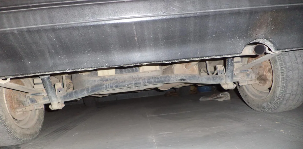
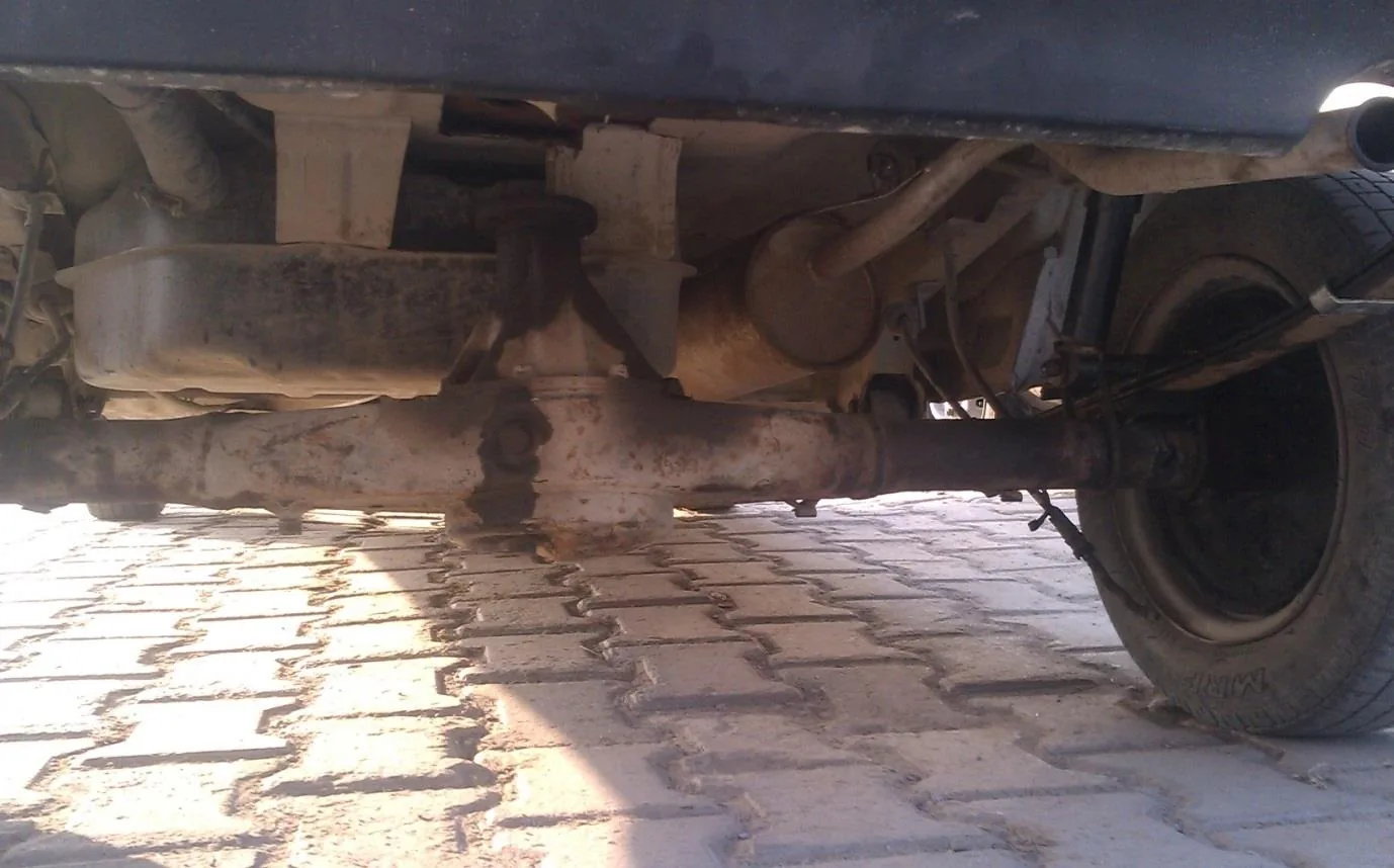
The base car is front-wheel drive. Its rear wheels sit on a dead axle, a beam that carries load but transmits no power. We took it out and fitted a live axle with a differential, so the motor had something to drive, and added an extra leaf to the rear springs to carry the weight of the batteries.
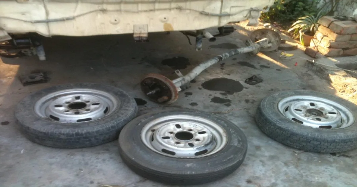
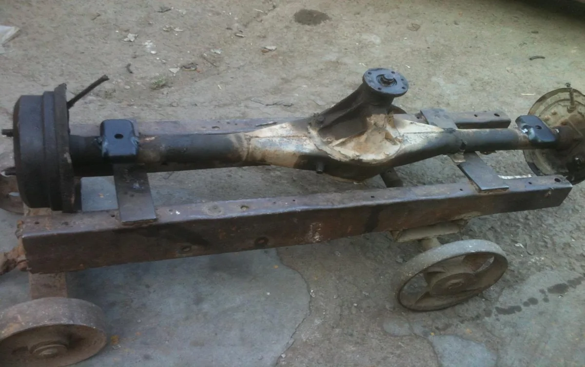
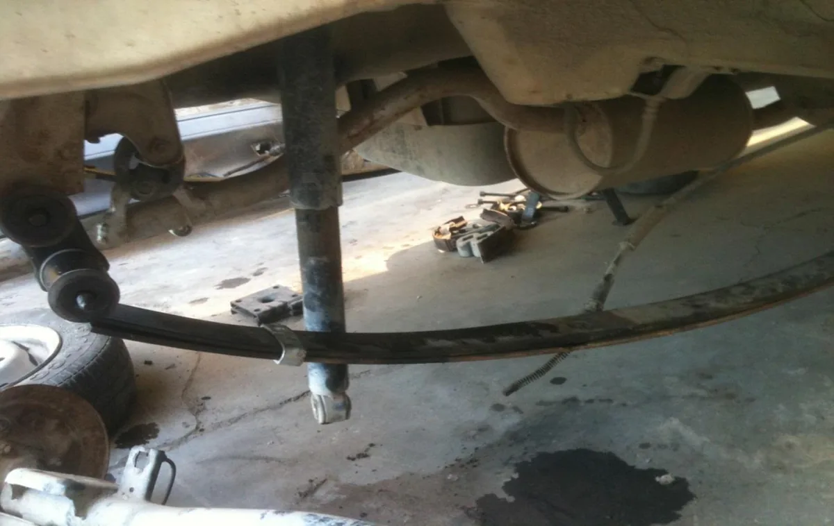
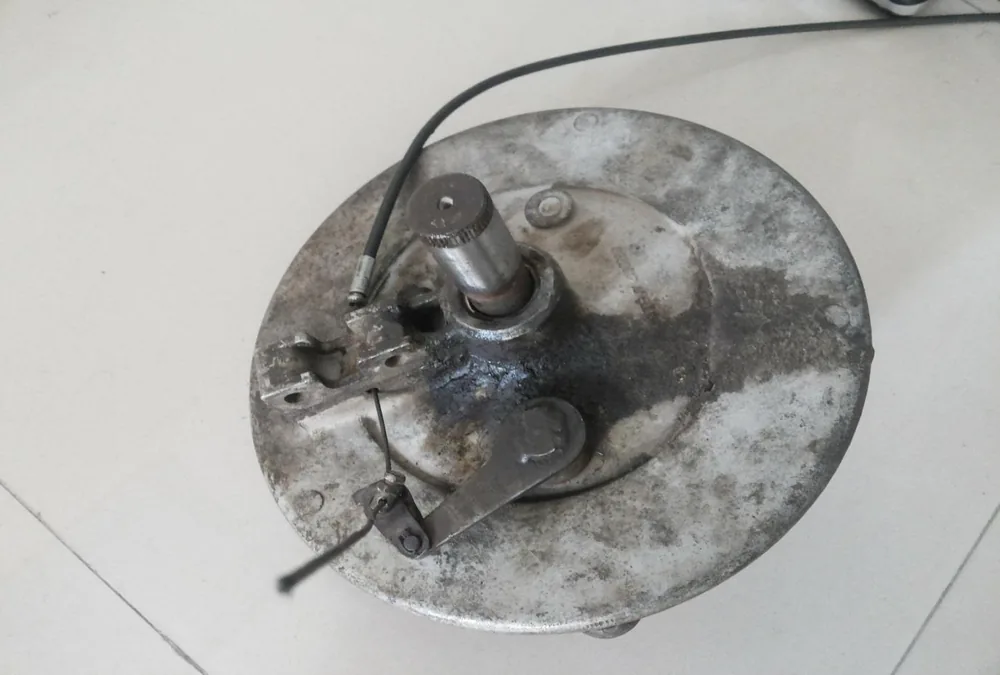
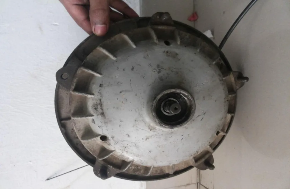
To switch between the two drivetrains, the motor has to be coupled to the axle in town and freed on the highway. We adapted a drum brake as a clutch for this, worked by a lever and cable from the cabin.
The finished car
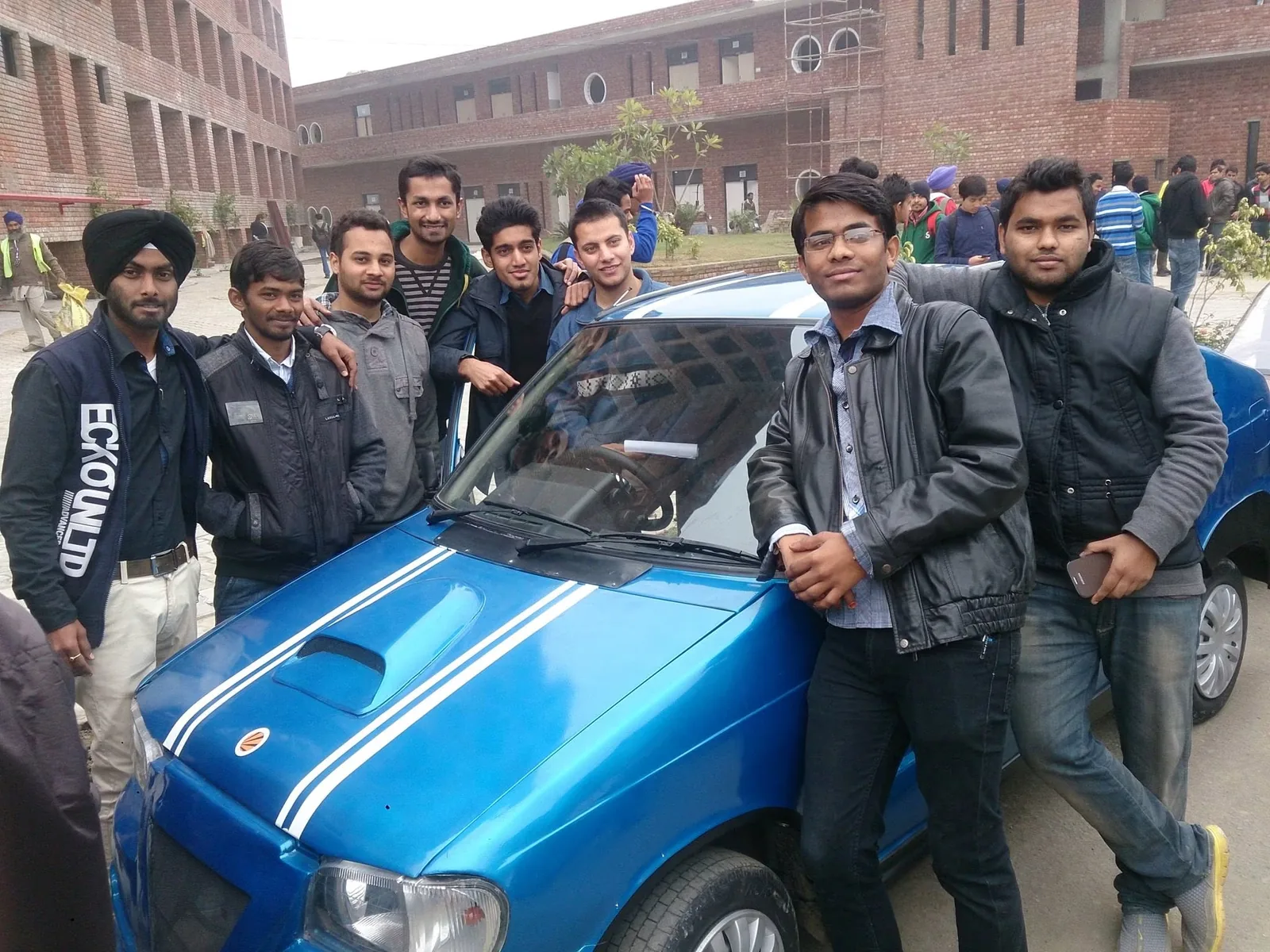
Repainted blue with white racing stripes and a hood scoop, the car went on to represent the university at Auto Expo 2014.
Specifications
| Front axle (engine) | Rear axle (electric) | |
|---|---|---|
| Source | 796 cc three-cylinder petrol, 28 L tank | Three 12 V, 200 Ah lead-acid batteries |
| Machine | 37 hp at 5000 rpm; 57 N·m at 2500 rpm | 10 kW brushless DC motor, 1440 rpm |
| Transmission | 4-speed manual | 12:1 gears, differential on a new live axle |
| Control | Stock clutch and throttle | Pedal-driven DC controller; DC-DC converter; 220 V charger |
| Used for | Highway | City, reverse and regenerative braking |
The car is 3.34 m long and 1.44 m wide on a 2.175 m wheelbase. With the batteries in the back it seats two, and the design curb weight rose to 950 kg, with a gross weight of 1300 kg.
My role
I led the student team that designed and built the car, coordinating its mechanical and electrical sub-teams, and the design of the split drive pattern, the regenerative braking system and the controller circuit is the subject of my B.Tech capstone report. I also designed and tested the liquid cooling loop for the batteries, including hose fittings and pressure testing, used Ansys to optimize the transmission and the coolant flow rate, and ran the FMEA. I sized the motor with the MATLAB vehicle-dynamics model, wrote the fabrication drawings, vendor specifications, bills of materials and assembly procedures, and bought the components within the cost budget and build schedule.